Fast Automation Deployment
Heavy Machinery
Computer Vision
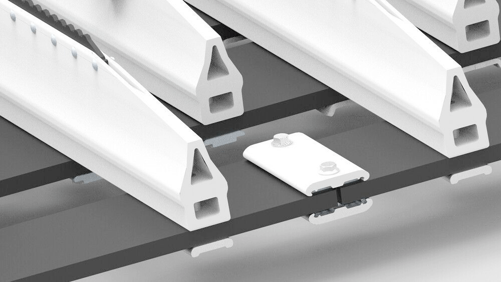
Screws on the track assembly
During track assembly for a snowcat, an automated torque wrench in the factory gave unreliable screw tightness detection using torque feedback alone. Our team used a Lidar and a simple gantry system to measure how far into the threads each screw was seated, and sends an OK / Not OK signal to the main PLC that controls this step in the assembly process.
Very high accuracy, the Lidar can detect a few turns of variation between screws
Our solution was developed, tested, and integrated into a production line within a few months
Approach
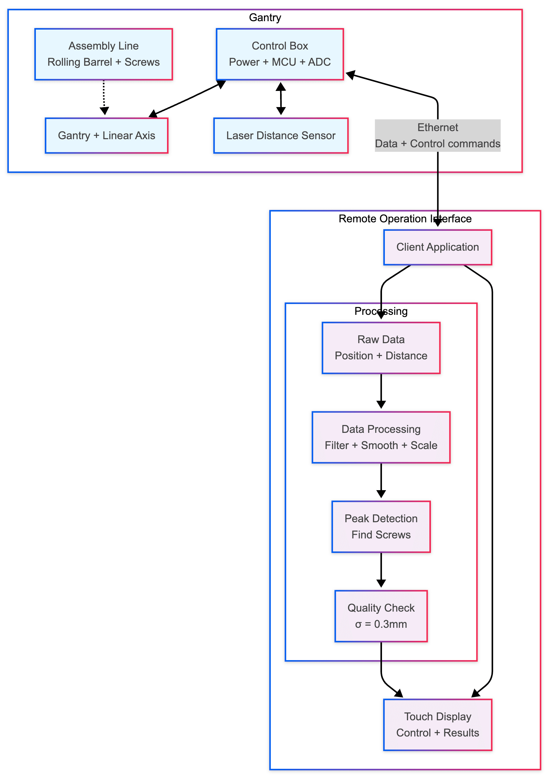
When screws move through the assembly line, a gantry system activates and sweeps its laser sensor across each row, measuring distances while tracking position to create a detailed surface profile. The control system collects this data and streams it to the operator interface, where software algorithms clean the measurements, remove noise, and convert readings to physical dimensions.
The system then searches for screw head signatures using pattern matching, identifies each screw's location, and calculates how far each one protrudes from the plate surface. By comparing these measurements against expected values, the optical system delivers reliable tightness verification with a standard deviation of 0.3mm from ground truth for properly tightened screws, replacing unreliable torque monitoring with precise visual inspection that meets industrial quality standards.
Architecture
Gantry System
- Custom-designed gantry framework mounted around the assembly mechanism
- Multi-axis adjustment capabilities (height and angle) for optimal laser range and minimal reflections
- Integrated spindle assembly for precise laser positioning along scanning axis
- Flexible positioning enables adaptation to various product configurations
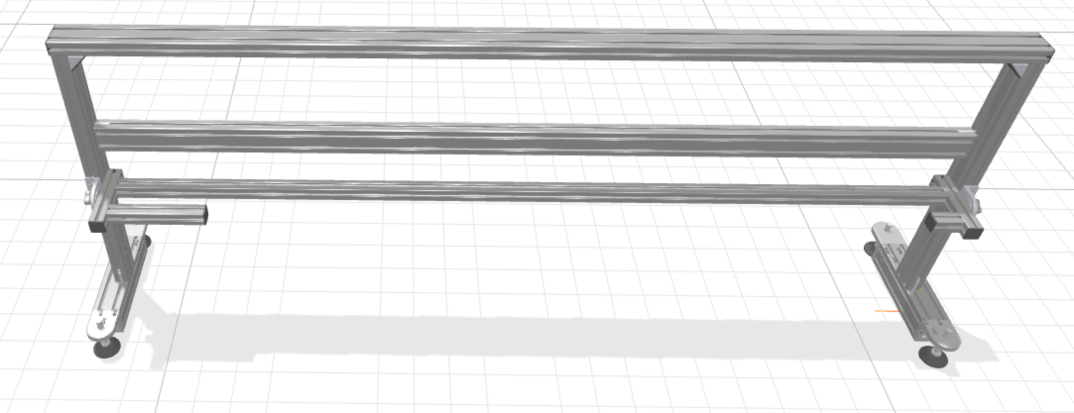
CAD model of the gantry carrying the linear actuator and the laser
Control Integration
- Self-contained control box mounted within gantry structure
- Dedicated power supplies for laser sensor, motor drive, and control electronics
- Distributed control architecture with specialized boards:
- Motor control board for spindle positioning
- High-resolution ADC board for laser signal processing
- Central microcontroller for synchronized data acquisition
Communication Infrastructure
- Ethernet communication over 10BASE-T1S
- Real-time data transmission between measurement system and operator interface
- Remote touch display interface running an integrated QA software
Data Acquisition
- Simultaneous sampling of motor encoder position and laser distance measurements
- Microcontroller synchronization ensures precise coordinate correlation
- Generates high-density coordinate datasets (x-position, distance) along scan profiles
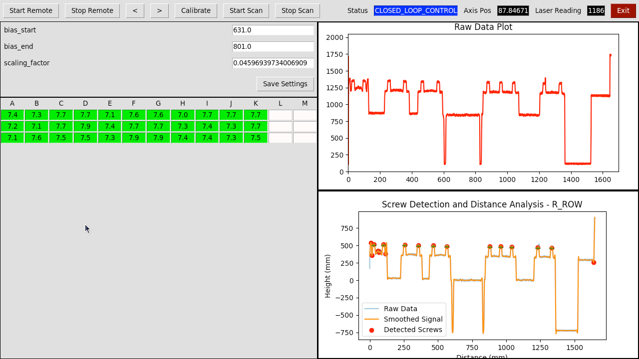
Example results of the QA tool after a few runs
Quality Assessment Algorithm
- Primary Check: Compares measured distance between screw head top surface and plate top surface against known screw head height specifications
- Secondary Check: Analyzes plate deformation patterns by comparing measured profiles against established baseline measurements
- Calibration System: Automated calibration routines accessible through touch interface
Operator Interface
- Touch-screen control for scan initiation/termination
- Real-time visualization of measurement data
- Integrated calibration tools and system configuration
- QA reporting and data logging capabilities
Workflow
Application at Bosch Rexroth
Quickly & iteratively increasing the degree of automation in quality assurance processes is key when introducing new versions of products.
Using modern technologies such as Lidar sensors, depth cameras, and laser profiles together with Motius' expertise in quick development, means that you can respond quickly as new demands for QA arise.